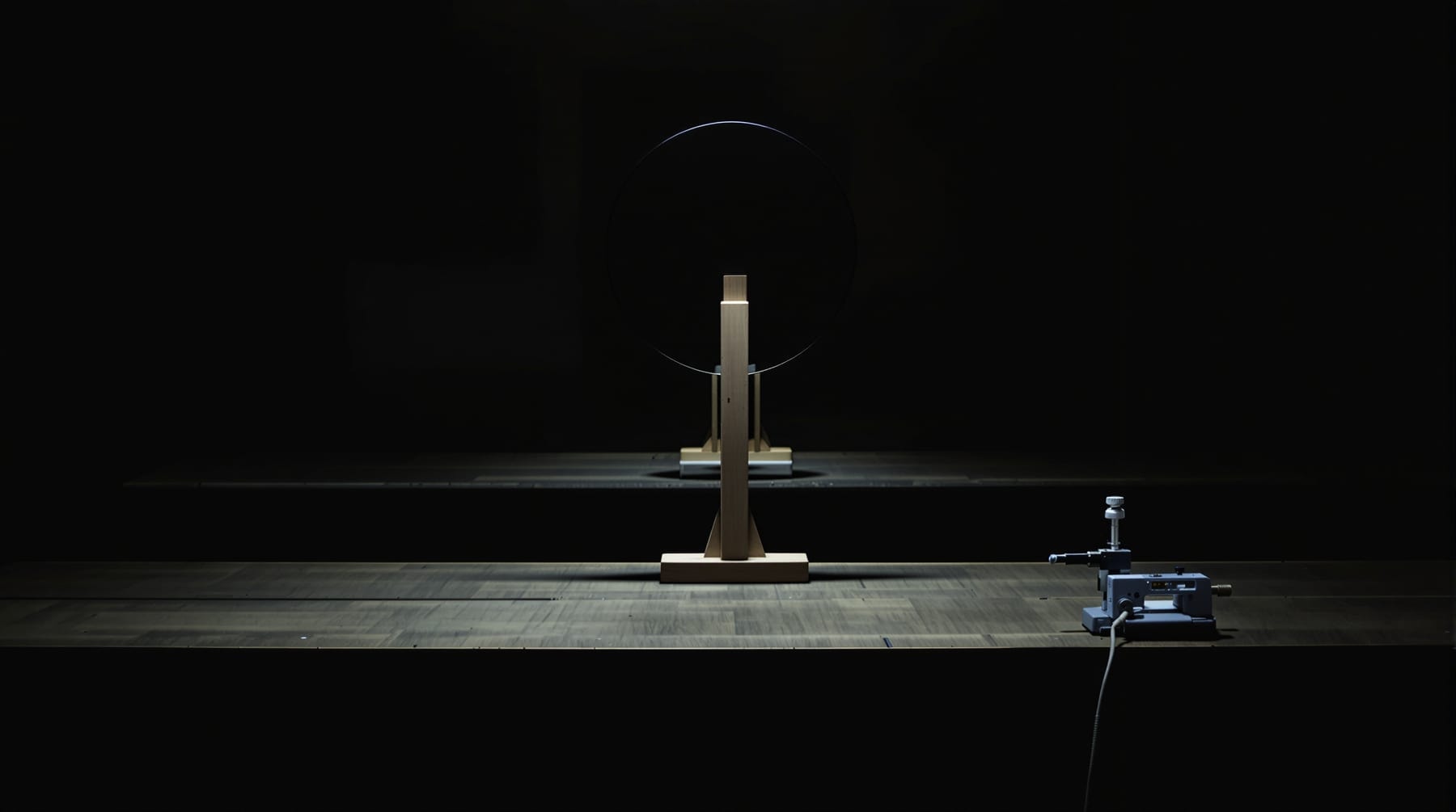
The reason amateurs can make optical surfaces accurate to a small fraction of a wavelength of light, using abrasive powder and a lump of pitch, is that they can measure what they have made. The measurement is the whole trick. Without it, figuring a mirror would be guesswork; with it, it becomes a controlled loop of small change and re-measurement.
The standard measurement is the Foucault knife-edge test, devised by Leon Foucault in 1858 and essentially unchanged since. It is startlingly sensitive — it will show surface departures of a few tens of nanometres to the naked eye — and it needs equipment you can build from scrap.
The principle
A concave mirror has a centre of curvature, at a distance of twice its focal length. A point source of light placed there is imaged by the mirror back to that same point — if, and only if, the mirror is a perfect sphere. That is the key insight: at the centre of curvature, a sphere returns all its light to one place.
Now put a knife edge at that returned image and slide it slowly across. If all the light is converging to exactly the point where the blade sits, the blade cuts every ray at once and the whole mirror face, seen from just behind the blade, darkens uniformly and simultaneously. If some zones of the mirror focus slightly nearer or further than others, those zones are cut at different moments, and instead of an even dimming you see a shadow sweep across the surface, with the errant zones standing out as light or dark regions.
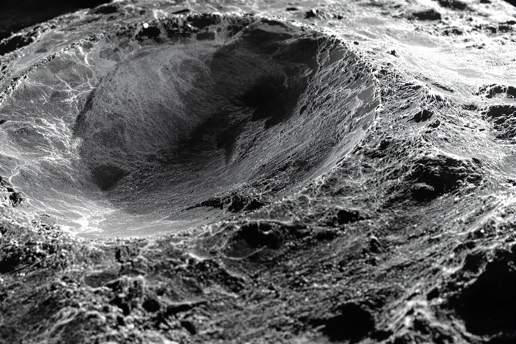
The result looks uncannily like a photograph of a landscape under low sunlight: the mirror appears as a relief map of its own errors, with hills, hollows and a raised or sunken rim. That visual quality is what makes the test so useful — you can see immediately what shape the error has before you measure anything.
Setting up
Work in a darkened room, with the mirror standing vertically in an adjustable stand at the far end and the tester on a bench at the near end, both at the same height. Six to eight feet of clear floor is plenty for a small mirror; the separation must equal the radius of curvature, so a 150 mm f/8 mirror needs 2.4 metres.
The tester carries an illuminated slit or pinhole and a knife edge, mounted so that the whole assembly can be moved along the optical axis by a measurable amount — a micrometer screw, or a fine-thread bolt with a graduated dial, reading to about one hundredth of a millimetre.
In the classic fixed-source, moving-edge arrangement, the light source sits slightly to one side of the axis and stays put, while the knife edge moves. Because the mirror returns the image of the source displaced the same distance the other side of the axis, the knife edge is positioned there. In the alternative arrangement the source and knife edge are mounted together and move as a unit, which changes the arithmetic slightly — the readings for a paraboloid come out half as large — so decide which you are using and stay consistent.
Three practical conditions matter more than beginners expect:
- Thermal stability. Air currents in the light path show up as drifting turbulence that makes readings impossible. Let the room and the mirror settle for at least an hour, keep your body and any lamp out of the path, and never test near a radiator or an open door.
- Rigidity. Everything must be immovable. A bench that flexes when you lean on it will produce beautifully repeatable nonsense.
- Darkness and dark adaptation. The differences you are looking for are subtle. Give your eyes time.
Reading zones
Qualitative shadows tell you the shape of the error. To quantify it you divide the mirror into concentric zones and measure each one separately, which is done with a Couder mask: a card placed over the mirror with pairs of matched openings cut at several radii, symmetrically either side of centre.
For each zone you move the knife edge along the axis until the two openings of that pair darken simultaneously, and record the reading. Working outward zone by zone gives a set of longitudinal positions describing where each annulus of the mirror actually focuses.
For a perfect sphere, every zone focuses at the same place and every reading is identical. For a paraboloid, the outer zones focus progressively further from the mirror, and the expected difference between the centre and a zone at radius r is
Δ = r² / R
where R is the radius of curvature, in the fixed-source arrangement. For a 150 mm f/8 mirror, with R of 2400 mm and an outer zone at r of 75 mm, the total spread from centre to edge comes to about 2.34 mm — a comfortably measurable quantity with a hundredth-millimetre screw. That single formula is the entire quantitative content of the test.
Compare your measured readings against the calculated ideal. Where a zone reads short of its target, that zone is too high — too little glass has been removed; where it reads long, the zone is too low. That directly tells you where to work, and the figuring section of the mirror-making page covers how.
Reading the shadows: the classic error signatures
- A sphere darkens flat and even, all at once, like a switch being thrown. Once you have seen it there is no mistaking it.
- A paraboloid tested at the centre of curvature shows a characteristic doughnut: a bright ring with a darker centre and a darker edge, changing as the knife edge advances. This is correct and expected — a paraboloid is supposed to look wrong under this test, because the test is measuring against a sphere.
- A turned-down edge shows as a narrow dark or bright crescent hugging the extreme rim, and it is the single most common and most damaging fault. Even a couple of millimetres of turned edge scatters light across the whole field and destroys contrast. It is worth masking the outer few millimetres of the mirror and re-testing to confirm.
- A central hole or raised zone appears as a distinct disc in the middle that darkens noticeably out of step with its surroundings — the signature of over-enthusiastic local polishing.
- Astigmatism shows as an asymmetry that rotates with the mirror when you turn the blank in its stand. That last part is the diagnostic: if the pattern stays fixed relative to the room, you are looking at a stand problem, a stress problem or air currents. If it turns with the glass, it is in the glass.
The Ronchi test
An easier alternative worth having alongside the knife edge. Replace the blade with a Ronchi grating — a fine ruling of parallel lines, typically around one hundred lines per inch — and look through it at the mirror from near the centre of curvature.
Instead of shadows you see a pattern of dark bands crossing the mirror face, and their shape reports the figure directly. A perfect sphere gives perfectly straight, parallel, evenly spaced bands. A paraboloid tested at the centre of curvature gives bands that curve outward in a characteristic barrel shape. A turned edge bends the ends of the bands sharply. Zonal errors produce visible kinks.
The Ronchi test is far less sensitive than the knife edge and much less quantitative — you cannot easily extract numbers from it. What it is excellent at is fast qualitative feedback: it takes seconds, it needs no mask and no measurement, and it shows the overall shape at a glance. The sensible workflow is to use Ronchi constantly during figuring to see which way things are moving, and the knife edge with a Couder mask periodically to find out where you actually are.
Knowing when to stop
The traditional standard is the Rayleigh criterion: a wavefront error no greater than a quarter of a wavelength produces an image effectively indistinguishable from a perfect one. Many amateur mirrors are better than that; many perfectly good telescopes are slightly worse and give excellent views.
Two cautions. First, the atmosphere over the Fraser Valley will limit you far more often than a small figure error will — on most nights here, seeing is the binding constraint and a difference between one-eighth and one-quarter wave is invisible. Second, more first mirrors are ruined by continuing to chase perfection than by being stopped too early. When the readings are within tolerance and the shadows look smooth, clean up and send it for coating.
For the wider theory of optical testing, Amateur Telescope Optics covers the mathematics properly, and the Stellafane ATM pages collect a great deal of accumulated practical experience with both tests.