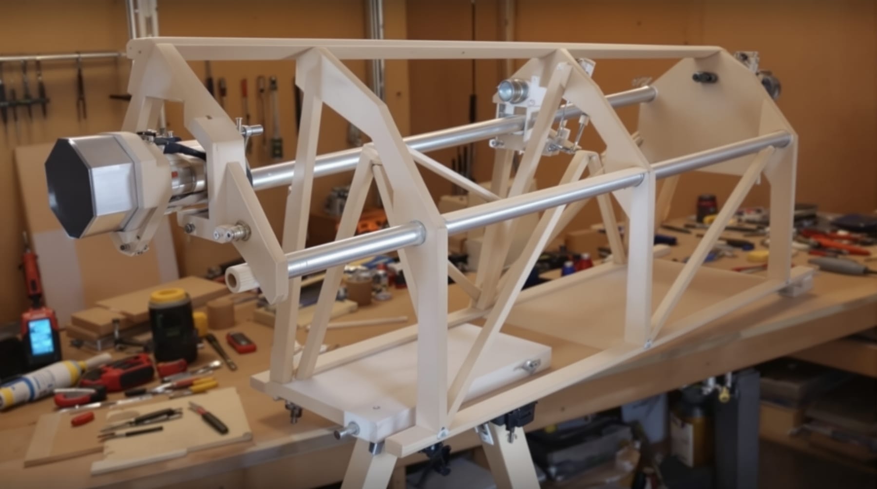
A finished mirror is only the optical half of a telescope. The other half is a structure that holds the mirror without bending it, holds a flat diagonal at exactly the right place, holds an eyepiece where the light comes to a focus, and does all of that rigidly enough that the image does not shake. None of it requires precision machining. A competent job with plywood, hand tools and patience produces a telescope indistinguishable in use from a commercial one.
This page covers the design decisions and the reasoning behind them. It assumes you have a primary mirror — see grinding and polishing a telescope mirror — or have bought one.
Deciding the geometry first
Before any wood is cut, three numbers need settling: the primary's diameter and focal length, which you already have; the size of the diagonal; and the distance from the diagonal to the focal plane. Everything else follows.
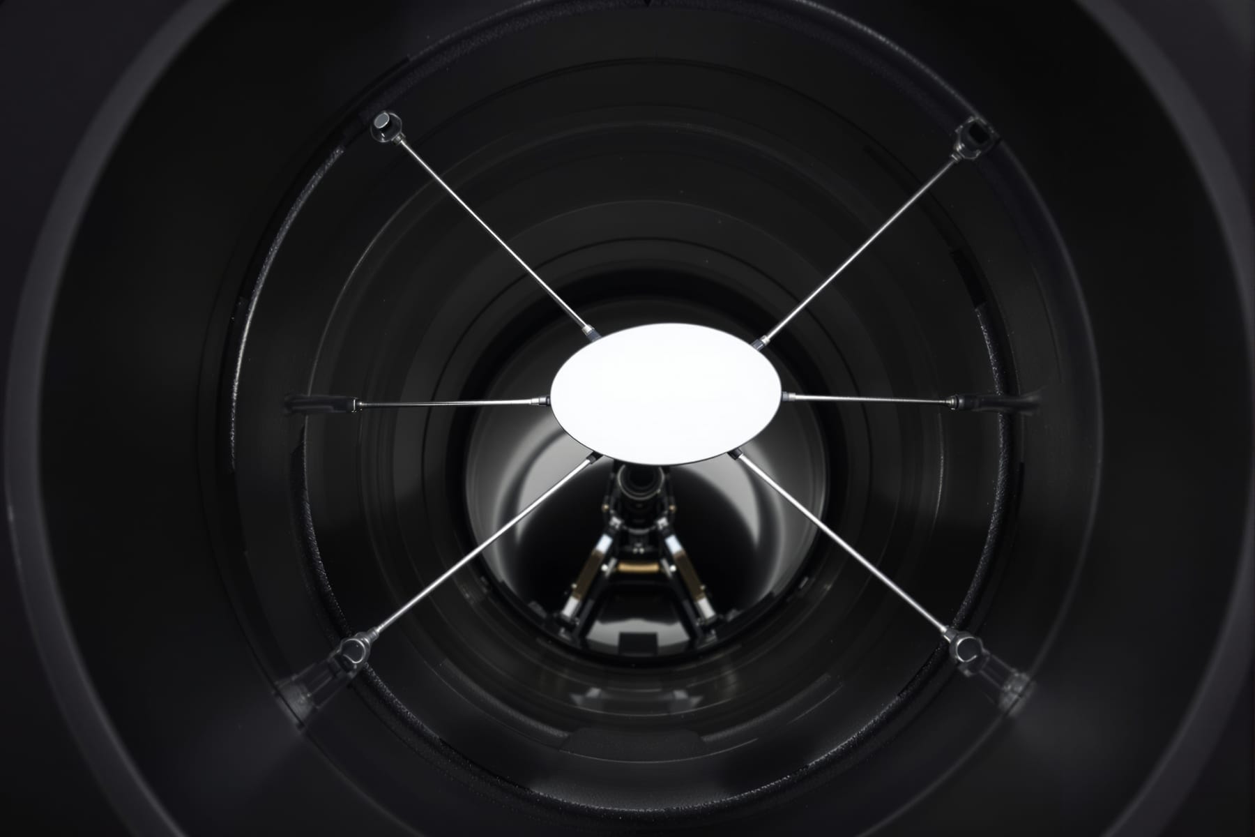
The Newtonian layout is simple. Light travels down the tube, reflects off the concave primary at the bottom, converges back up the tube, and is intercepted just short of focus by a small flat mirror set at forty-five degrees, which throws it out through the side of the tube to an eyepiece. The diagonal exists purely because your head would otherwise sit in the light path — at prime focus you would block the very light you were trying to observe.
Sizing the diagonal
This is the one genuine calculation in the build, and it involves a real trade-off. Too small a diagonal and the outer part of the field is not fully illuminated, so the image dims toward the edges. Too large and it obstructs more of the primary, reducing contrast and strengthening the diffraction pattern around bright objects.
The standard formula for the diagonal's minor axis is
dminor = ((D - d) × L / F) + d
where D is the primary's diameter, F its focal length, L the distance from the diagonal's centre to the focal plane, and d the diameter of the fully illuminated field you want at the focal plane.
Two of those need explanation. L is set by physical necessity: the focal plane has to sit far enough outside the tube for an eyepiece and focuser to reach it, so L is roughly the tube radius plus the focuser's minimum height plus a little margin. Making the tube fatter than it needs to be therefore forces a larger diagonal, which is why unnecessarily oversized tubes are a false economy.
d is a choice. It is the diameter of the region at the focal plane that receives light from the entire primary. A common choice for a visual telescope is around 15 to 20 mm; wanting a large fully illuminated field for photography pushes it up and pushes the diagonal size up with it.
The governing constraint is that the diagonal's minor axis should not exceed about 20 to 25 per cent of the primary's diameter. Beyond that the central obstruction starts to have a visible effect: contrast on planetary detail falls off and the diffraction rings around bright stars strengthen noticeably. For visual use, aim for the smallest diagonal that gives an acceptable illuminated field.
A note on why the diagonal is elliptical. It is a flat mirror intercepting a circular converging cone at forty-five degrees, and the intersection of a cone with a plane at that angle is an ellipse — with a major axis about 1.41 times the minor. Diagonals are always specified by their minor axis, which is the dimension that matters optically.
Field of view, and why it constrains everything
The true field a telescope shows is the eyepiece's apparent field divided by the magnification. In practice most visual observing happens with a true field between about half a degree and three-quarters of a degree — that is, between one and one and a half Moon diameters. That is the range the illuminated field, and therefore the diagonal, needs to serve. Understanding this stops you specifying an enormous diagonal for a field you will never use.
The tube
A closed tube of thin plywood, cardboard concrete-form tube or rolled aluminium keeps stray light out and the optics clean, and is simple. An open truss structure — a mirror box, an upper cage carrying diagonal and focuser, and a set of removable poles between them — is lighter, dismantles for transport, and cools far faster. Cooling matters more than beginners realise: a mirror warmer than the surrounding air generates a convection plume directly across the light path, and the resulting "tube currents" degrade the image badly. On this coast, with clear nights that drop temperature fast, an open structure is genuinely worth the extra complexity for anything above about 200 mm.
Whichever you build, blacken the interior thoroughly. Flat black paint is a start; a flocked light-absorbing lining opposite the focuser is better, and it makes a visible difference to contrast because that is exactly the patch of tube wall the eyepiece is looking at.
The mirror cell
The cell supports the primary from behind, and the requirement is that it must support it without distorting it. A mirror resting on three fixed points sags between them under its own weight, and for a thin or large mirror that sag is enough to spoil the figure. The standard answer is a floating multi-point support: three pivoting triangles carrying nine contact points, or six-point and eighteen-point variants for larger mirrors. For a 150 mm mirror a simple three-point cell is entirely adequate; from about 250 mm upward a nine-point cell becomes worthwhile.
Two rules that get broken often. The mirror must never be clamped tightly — retaining clips should overlap the front face by a couple of millimetres with visible clearance, so the mirror is prevented from falling out but is otherwise free. And it must be supported at the edge against sideways movement by a sling or soft pads at the sides, not resting hard on the bottom of the cell, which produces astigmatism.
The cell also carries the three collimation adjusters that tilt the whole assembly. Springs and locking screws are the usual arrangement.
The spider and diagonal holder
The diagonal is held in the light path by a spider: thin vanes reaching in from the tube wall. Those vanes are what produce the four-pointed diffraction spikes around bright stars in Newtonian images. Thin, straight, accurately aligned vanes give clean spikes; thick or bent vanes give a smeared mess. Aim for vanes no more than about half a millimetre thick, tensioned so they are genuinely straight.
The diagonal holder must allow three adjustments: rotation about the tube axis, tilt, and position along the tube. All three need to be settable and then locked. Glue the diagonal to its holder with three small dabs of silicone rather than clamping it, for the same reason as the primary — a clamped flat is a bent flat.
The focuser and its placement
The focuser's position along the tube is determined by the geometry: it must sit so that the eyepiece's focal plane lands at the distance L you used in the diagonal calculation. Get this wrong and either you cannot reach focus at all, or you can only reach it with the eyepiece hanging out of the drawtube.
A rack-and-pinion or Crayford focuser bought ready-made is a sensible place to spend money, because a focuser that shifts the image sideways as it racks in and out is a permanent irritation. Whatever you use, the drawtube must be square to the tube axis — a focuser mounted at a slight angle cannot be collimated out.
The mount
For a home-built Newtonian, the Dobsonian alt-azimuth mount is very hard to beat: a plywood rocker box in which the tube swings in altitude on two side bearings and the whole box rotates in azimuth on a ground board. There is nothing to it, it costs almost nothing, and it is enormously more stable than an equatorial mount of comparable cost.
The bearing surfaces are the whole art. The traditional combination — plastic laminate against textured PTFE pads — gives the characteristic Dobsonian feel: enough friction to hold position with no locks at all, little enough to nudge smoothly by hand. The single most common building error is making the motion too free, so that a telescope which balances perfectly with one eyepiece tips when you fit a heavier one. Slightly stiff is right.
Collimation
The finished telescope needs its optics aligned before it will perform, and it will need re-checking periodically — after transport, and occasionally as wood moves with humidity. The sequence is: square the focuser; centre and rotate the diagonal under the focuser so that the primary appears centred in it; then tilt the primary so its own reflection is centred. A simple sight tube and a Cheshire eyepiece do the whole job, and a small paper ring stuck at the exact centre of the primary — which is in the shadow of the diagonal and so costs nothing optically — makes it far easier.
Collimation sounds forbidding and takes about five minutes once learned. It is the difference between a home-built telescope that shows what its aperture should and one that disappoints for reasons its owner never diagnoses.
References
For the optical theory behind the obstruction, illumination and diffraction trade-offs discussed above, Amateur Telescope Optics is thorough and free. For construction plans, dimensioned drawings and a large body of accumulated advice from people who have built many of these, the Stellafane ATM pages remain the best starting point. Further reading is collected under resources for telescope makers, and once it is finished, the seasonal sky guide will tell you where to point it.