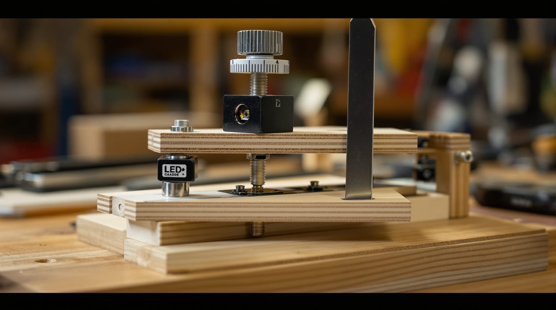
The Foucault tester is the piece of equipment that makes amateur mirror making possible, and it is also, pleasingly, the cheapest thing in the workshop. Everything it does is a matter of geometry and rigidity; there is no precision optics in it at all. A tester built from scrap timber, a bolt and an LED will measure a mirror surface to a fraction of a wavelength of light, and a commercially made one will not do it any better.
This page describes a simple fixed-source, moving-edge tester, which is the easiest arrangement to build and to reason about. For what the tester is for and how to use it, see testing a mirror with a knife-edge tester.
What it has to do
Four things, and no more.
- Produce a small, bright point or slit of light that can be positioned close to the optical axis.
- Hold a straight, sharp edge immediately beside the returned image of that source.
- Allow the edge to be moved along the optical axis by a measurable amount, with a resolution of about one hundredth of a millimetre.
- Allow the whole assembly to be moved across the axis so the edge can be brought into the returned beam, and then stay exactly where it is put.
Everything else is convenience. Note in particular that rigidity matters more than precision: an assembly that flexes by a few hundredths of a millimetre when you touch the adjusting screw will produce readings that look repeatable and are meaningless.
The stage
The usual arrangement is two stacked stages. The lower one slides transversely — across the beam — and simply needs to move smoothly and then hold position; a plywood platform on hardwood runners with a clamp screw does it perfectly well. The upper stage carries the source and the knife edge and moves along the axis, and this is the one that must be measurable.
The classic mechanism is a fine-thread screw driving the upper stage against a return spring. A metric bolt with a 0.5 mm pitch advances the stage half a millimetre per turn, so a disc fixed to its head and divided into fifty parts reads to one hundredth of a millimetre directly. A better option, if one comes to hand, is a discarded micrometer head or a dial indicator, either of which gives calibrated readings with no arithmetic at all. A dial indicator reading to 0.01 mm from a tool shop costs very little and is entirely adequate.
Whatever you use, the spring return is important: driving the stage in both directions with the screw introduces backlash, and backlash is indistinguishable from a figure error. Always take readings advancing in the same direction, and if you overshoot, back off well beyond the target and come back onto it.
The light source
A single white LED behind a small aperture is ideal. It is bright, it runs cold — which matters, because heat in the light path creates the air currents that ruin the test — and it can be run from a battery.
The aperture itself can be a pinhole of about half a millimetre punched in thin metal shim or aluminium foil, or a narrow slit. A slit oriented parallel to the knife edge gives a brighter image and is easier to work with; a pinhole is simpler to make. Either way, mount it so it can be moved sideways relative to the knife edge by a few millimetres, because the source and the returned image must sit symmetrically either side of the axis, and the correct spacing depends on the mirror.
Shroud the source thoroughly. Any stray light escaping toward the mirror, or toward your eye, reduces the contrast of the shadows and costs you sensitivity. A small box with a single hole in it, painted matt black inside, is worth the ten minutes it takes.
The knife edge
Almost anything genuinely straight and thin will do: a razor blade, a snapped-off utility blade, a steel rule, or the edge of a piece of thin sheet metal. Check it by sighting along it against a light — a nick or a burr will show up in the test as a fixed artefact.
Mount it vertically, perpendicular to the direction of travel, and close beside the light source. It should be adjustable sideways independently of the source, and once set it must not move.
The mirror stand
Equally important and frequently neglected. The mirror stands vertically at the far end of the room and needs to be tilted and swivelled slightly to aim the returned beam back at the tester. A simple wooden frame with the mirror resting on two pegs at the bottom and leaning against a padded back, with a screw adjuster for tilt, is sufficient.
The critical requirement is that the mirror must be supported without being stressed. Clamping a mirror at the edges, or standing it on a hard point, bends it — and a bend of a few hundred nanometres is exactly the size of the thing you are trying to measure. Support it on two points at roughly thirty degrees either side of bottom centre, rest it against soft backing, and never clamp it. If the astigmatism you see in the test rotates when you rotate the mirror in the stand, it is in the glass; if it stays put, it is your stand.
Building for the room you have
The tester and the mirror must be separated by the radius of curvature, which is twice the focal length — 2.4 metres for a 150 mm f/8 mirror, and more for anything longer. A garage, a hallway or a basement will usually do. It is worth building the tester onto a base that can be clamped to a bench or a heavy board rather than expecting a table to be steady, and worth being able to set the whole thing up in the same place each time.
Two last practical points. Test in the dark and give your eyes twenty minutes to adapt; the differences you are looking for are small. And let everything reach thermal equilibrium — an hour is not excessive — because convection currents rising off a warm mirror, a warm tester or your own body will produce drifting turbulence that swamps the measurement entirely. On a coast with cool damp evenings, a room that has been closed up all day is a better test space than one that has just been opened.
With the tester built, the procedure is on the testing page, and the figuring it feeds into is on the mirror-making page. Further construction ideas and variant designs are collected in resources for telescope makers and at Stellafane.